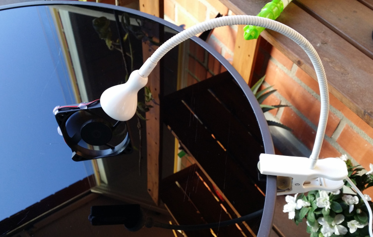
A gooseneck fan from an IKEA Jansjö
Everyone knows the IKEA Jansjö lamp - it’s small, light, and flexible, both figuratively and literally. Just the right spot lamp for all kinds of smaller work - clip it to your table, shelf, cabinet, whatever, then bend and point as necessary. Its low price and widespread availability has lent it to a plethora of hacks: a magnet base hack, another one, and another, and still another, a lighted sheet music stand, a globe night light, a flamingo-shaped lamp, and a ton of others.
I was practicing hot-air desoldering recently, and, although I did so on my balcony, I still had to breathe in quite a bit of fumes produced by heated PCBs and components (ah, the smell of popping electrolytics!). So I thought a bit of extra air movement could get them away from me, but my soldering fume extractor would have been useless beside an already powerful air stream from the hot-air gun. That’s when I thought something like a smaller fan closer to my face would be just about right, something like this one, attached to a desk lamp. I was already using a Jansjö while desoldering, we had a couple extra from a flea market (who would even sell them off?), and I thought putting a fan on one would be just the thing.
Yeah a black Jansjö would be better, but I had a white one, so here it is. What follows is how I made it, and how you can make one. I wanted to be able to put the lamp back together and reuse the fan, if my plan didn’t work, so I proceeded carefully, trying to preserve everything. However, I’m sure there are a thousand ways to do this, and it’s up to you how gentle/barbaric you’re going to be with yours. This is just my way.
DISCLAIMER: I’m in no way responsible for any damage caused to the lamp, yourself, your dog, or your apartment, as a result of following my instructions. This will also void the lamp’s warranty. Proceed at your own risk!
You’ll need:
- An IKEA Jansjö, with a base of your choice. I.e. a clip like I used, a floor stand, a table stand - whatever you like, the lamp fixtures themselves seem to be the same, and that is what matters.
- A fan. If you’re going to use my mounting method, then it shouldn’t be thicker than 10mm, which is what I used. Mine had 60mm sides, but smaller or larger would also work, as long as the goose neck can hold its weight. I used a Y.S.TECH FD126010LB (no affiliation with the seller). This one is not cheap, but is supposed to last long, being brushless and seemingly having ball bearings.
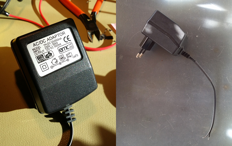
- A power adapter with a rating corresponding to the fan you have. The one Jansjö has, while being powerful enough, has voltage (4V) which is too low for any but the smallest fans. It must output DC (direct current), as small fans are usually DC-powered! Make sure the adapter’s claimed maximum current is at least twice as much as the current consumed by the fan, as those are never exact. I picked a 12V 500mA-rated power adapter from a flea market for my 140mA-rated fan.
- A basic multimeter to test polarity when connecting the power supply.
- Soldering iron and soldering wire.
- A piece of heat-shrink tubing or electrical tape for insulating soldered wires.
- A glue gun with a glue stick, or something else to fix the wire to the assembly. Electrical tape will probably hold it for a while.
- A piece of thin sheet metal, like tinplate, e.g. from a tin can.
- Metal shears to cut the metal.
- Pliers to hold and bend it.
- A small diameter machine screw with a flat head and a corresponding nut. I used an M3 with a nylon locking nut.
- A drill, a 2mm drill bit, and another one, somewhat larger than the screw diameter, but smaller than its head, so the screw can sink into the hole. I used a 3.5mm one, IIRC.
- Something thin and sharp to pull out the lens fixture, I used two pins.
- Something a bit thicker, like two small flat-head screwdrivers to help them.
That’s one hell of a list, but all I can say is improvise if you lack something.
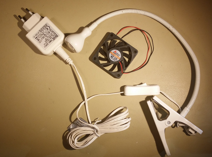
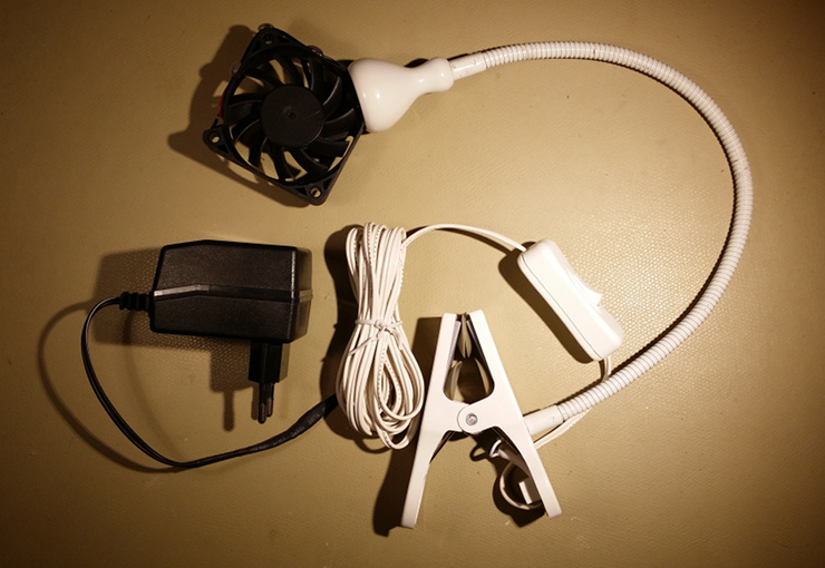
The lamp and the fan I started with:
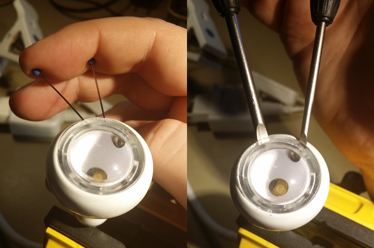
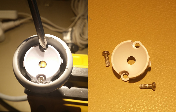
First I removed the lens fixture. It’s hard to fit anything under it, so I
used two pins helping each other, and squeezing the metal skirt gently to get
under the fixture’s lip. Then I was able to put two small flat screwdrivers
there.
I worked my way around the fixture levering it up until it popped out, freeing
the lens and revealing the reflector. You can see the tabs which were holding
the lens fixture, on the sides of the reflector.
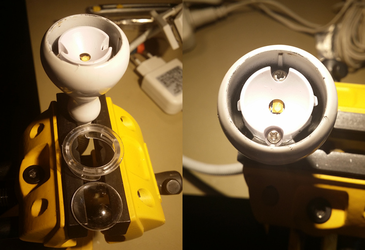
Unscrew the reflector. It’s held by 2mm cross-head machine screws. Save them.
Removing the reflector reveals the board with the LED and a few components.
De-solder the power supply wires and take the board out. Better do it with
pincers, as the thermal paste underneath will stick to anything.
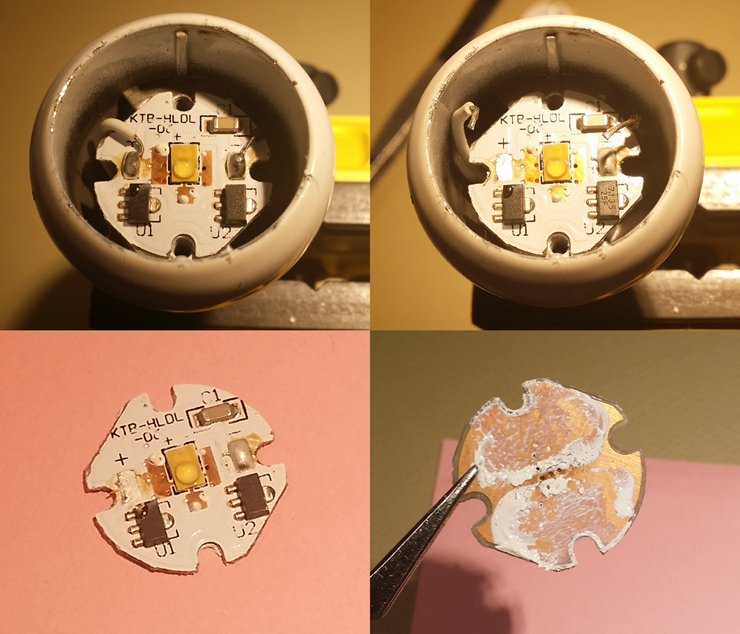
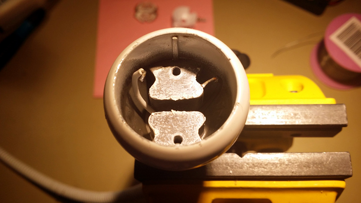
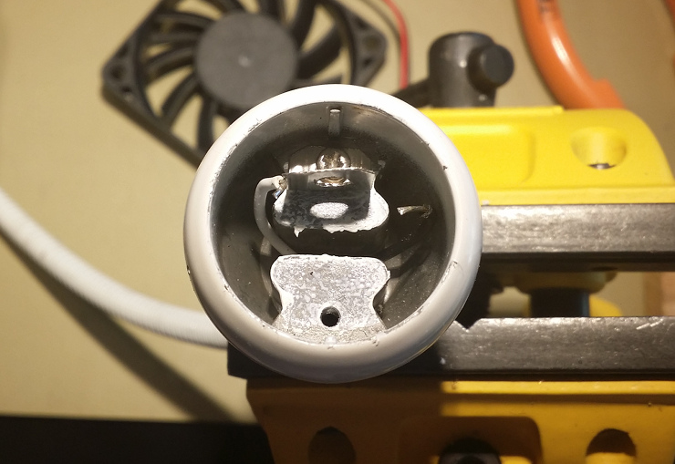
Here is our empty lamp. From this point on we will stop removing things from
this end and will be adding them. Note that some thermal paste is still there.
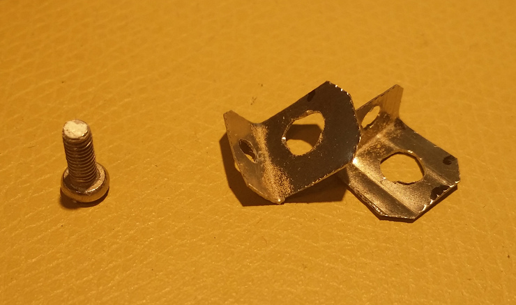
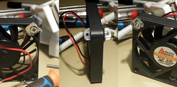
Next I made two angled braces (what’s the proper term?) for the fan, from the
thin springy steel I salvaged from an inkjet printer a while ago. This wasn’t
an exact job with the materials and tools I had. There was no measuring
involved and I mostly used my eye and trying to fit things together, but here
are a few tips. Drill 2mm holes for fixing the braces to the lamp base,
drill holes slightly larger than the screw to hold the fan, but smaller than
the screw’s head (I used an M3 screw and a 3.5mm drill bit). Position the
holes for the fan-holding screw somewhat lower than the ideal placement, so
that when you screw the assembly to the lamp base, the 2mm screws would pull
the fan in, push it against the lamp skirt, and hold it firmly in place. Also,
make sure that when the fan-holding screw is in, it still allows the smaller
lamp’s screws to be in place and turned. Here are the braces alongside a 2mm
screw from the lamp.
Don’t even think about holding the metal with your hands while drilling, unless you want your fingers finely shredded! The drill bit will inevitably lock up in the thin metal and it will start spinning with it like there’s no tomorrow. Hold the metal with a tool, e.g. pliers!
Here are the braces on the fan for a test. Note that you’ll have to take them
off again before proceeding.
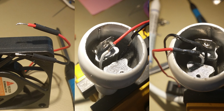
Next I attached the first bracket before soldering the fan wires, but it’s
probably easier the other way around. Don’t tighten that screw yet!
Don’t forget to put your heat-shrink tube on before soldering the wires.
I cut the fan wires a bit shorter before this, so there wouldn’t be any excess
when it’s fixed to the lamp.
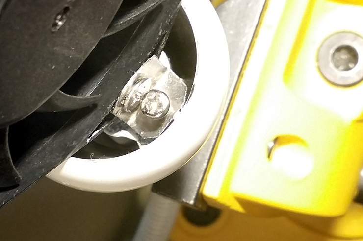
Now for the tricky bit. Put the fan-holding screw through the still unattached
bracket and then through one of the fan corner screw holes. Then bend the
already attached bracket outwards, towards the lamp skirt, so that you can put
the screw (which is in the fan) through it. Then slide the other bracket in
too, but don’t screw it in. Now you should be able to move the fan-holding
screw back and forth and also wiggle the fan around a bit. This should give
you enough flexibility to put the nut on the fan-holding screw. That and lots
of patience. Believe me, you’ll need it.
I admit I should have made more photos of this process, but at the time I wasn’t sure this is going to work, and it was difficult enough, so this will have to be another case of “how to draw an owl” meme.
Once you have the nut on and tightened, screw the other bracket to the lamp
and tighten both of the remaining screws, so that the fan is held in the lamp
skirt firmly. Try not to overdo it, so if you use a softer metal for the
braces they are not ripped, or the fan plastic doesn’t break. BTW, this is why
we needed the flat-headed screw for holding the fan - to be able to put the
second lamp-fixing screw in. Sorry for the over-exposure here.
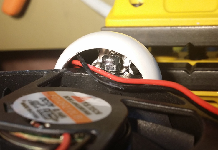
Next thing, you might want to fix the fan wire down so it doesn’t get broken from vibration, doesn’t obscure the air flow, and doesn’t get under the fan blades. I used some hot glue, but you might get away with some strong sticky tape. I also left some extra wire length on the fan, and oriented the wire entrance away from the lamp, because I wanted to be able to reuse the fan. The corner of the fan where wire enters is the weakest one, and I didn’t want to attach that to the lamp. No dedicated picture here, sorry, but see the top and the bottom ones.
Then replace the power adapter. Cut the lamp’s and power adapter’s cord at the
places of your choice and solder them together. Observe polarity! If you do it
wrong and you have a brushless fan, then its control electronics might not
work, or even (theoretically) burn out. A basic DC motor would work, but would
turn in the wrong direction, possibly resulting in a suboptimal air flow. Try
checking the fan frame for arrows showing the rotation and air flow directions
to make sure it’s right, or use your multimeter and check wire colors.
Do not repeat my mistake and do cut off the lamp’s cord before soldering and isolating the wires inside the lamp, so you can test which one is which from the power adapter side.
Anyway, I’ll pull the “draw an owl” here again, skip the
power cord soldering and insulation, and will rush you to the final picture:
I’m very pleased with the result. Although I still prefer to bend the goose neck itself, and more so when the fan is running, it is sitting in the lamp nice and tight and I can bend the lamp by pulling the fan as needed, without a hint of slack, or fear of breaking it off. I considered putting a wire mesh on both sides of the fan for safety at the cost of efficiency, but where is the fun in that? Make your own choice here, though. Otherwise, the fan is quiet, airflow is great, and I’ll be testing it with my desoldering process soon!
Even if you don’t do it exactly as I did (completely understandable), I hope my HOWTO inspires you to do something like this yourself. Enjoy your hacking!
Comments
If you'd like, leave your comment at the issue page for this post and it will appear below.